
Soldering Iron Temperature Control Circuit Diagram
Page 1 OLED T12 Soldering Iron USER MANUAL.; Page 2 10 degrees) • Tin: 5 seconds (24V) Package included • 1pc T12 Adjust control handle • 1pc T12 normal iron tip as you choose option. Features: • Mini T12 Portable Soldering iron • Large power: 72W (Maximum) •. Page 3 1. Functions of press key and display description • "Push to the right" means move to the right or increase.
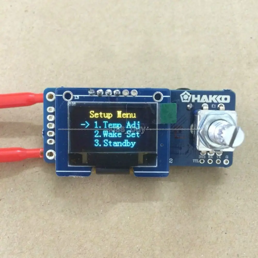
dykbT12OLEDDigitalSolderingIronStationTemperatureControllerBoardLCDdisplaypanelFOR
The Hakko T12 soldering tips are amazing tools for soldering: they heat very fast and can reach very high temperatures in a short period of time. Each tip have a built-in thermo couple to control its temperature very accurately. Also, using appropriate handle, you can replace the tip on the fly in 1 second. The main features of this controller are:
HAKKO T12 OLED Digital Soldering Iron Station Temperature Controller Board new Other Circuit
Note that while the product is advertised as a T12 soldering iron this is just the name of its ubiquitous soldering tip (Hakko T12). So I needed a more specific name for it and chose the label on its PCB: Pen Solder V3 or short: PSV3.. "STM"32F030 Pinout. 1: BOOT0 -> 10k to GND; 4: NRST -> filtered VDD.
2pcs T12 KU Solder Iron Tips High Quality T12 KU Lead Free Soldering Iron Tip For HAKKO
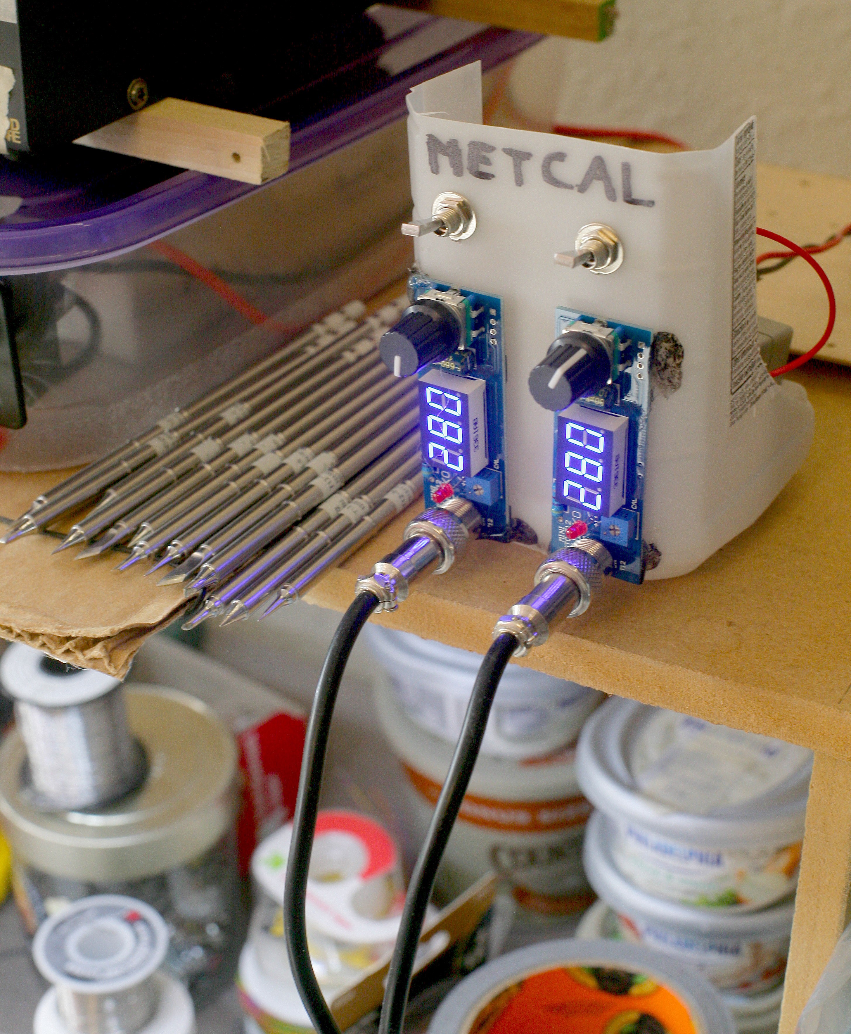
This is a second release of combined soldering iron controller for Hakko T12 tips and 858D rework station based on STM32 micro controller. The controller supports using both devices at the same time. The project was created because Maker B R requested it very much. Hope, it would be useful for many enthusiasts like me. Combined station at work
EEVblog 596 World's Cheapest Soldering Station Yihua 936 Page 1
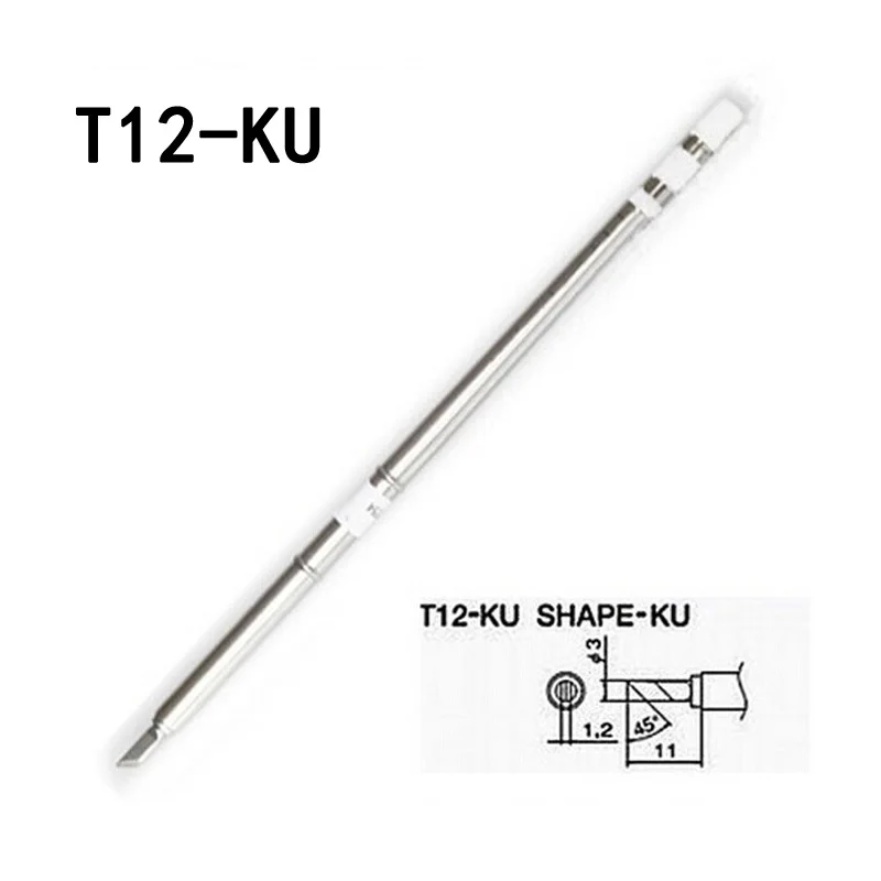
Adjust the potentiometer so the bar would be as near to the label as possible. Then press the encoder handle for about 2 seconds to turn the iron off and finish the procedure. It is recommended to use the thick tip that produce the highest voltage when performing the tune procedure. For example, T12-K, T12-D52 or so.

Digital Soldering Iron Station Temperature Controller Kits For HAKKO T12 Handle eBay
This is a three-channels combined soldering iron rework station for Hakko T12, JBC C245 and 858D Hot Air Gun based on STM32 micro controller. The soldering controller uses ili9341 TFT display with SPI interface without touch-screen.
Hakko T12 controller with JBC T245 iron Page 1
Soldering - the T12 experience Started 29th March 2018 Buying a temperature controlled soldering iron off ebay (see Solder for how I got here) I did not know the context - it was something cheap to play with. It turns out what I had was a Hakko 936 soldering station clone with a clone 907 handle. The Hakko bits are series T4 (or 900M).
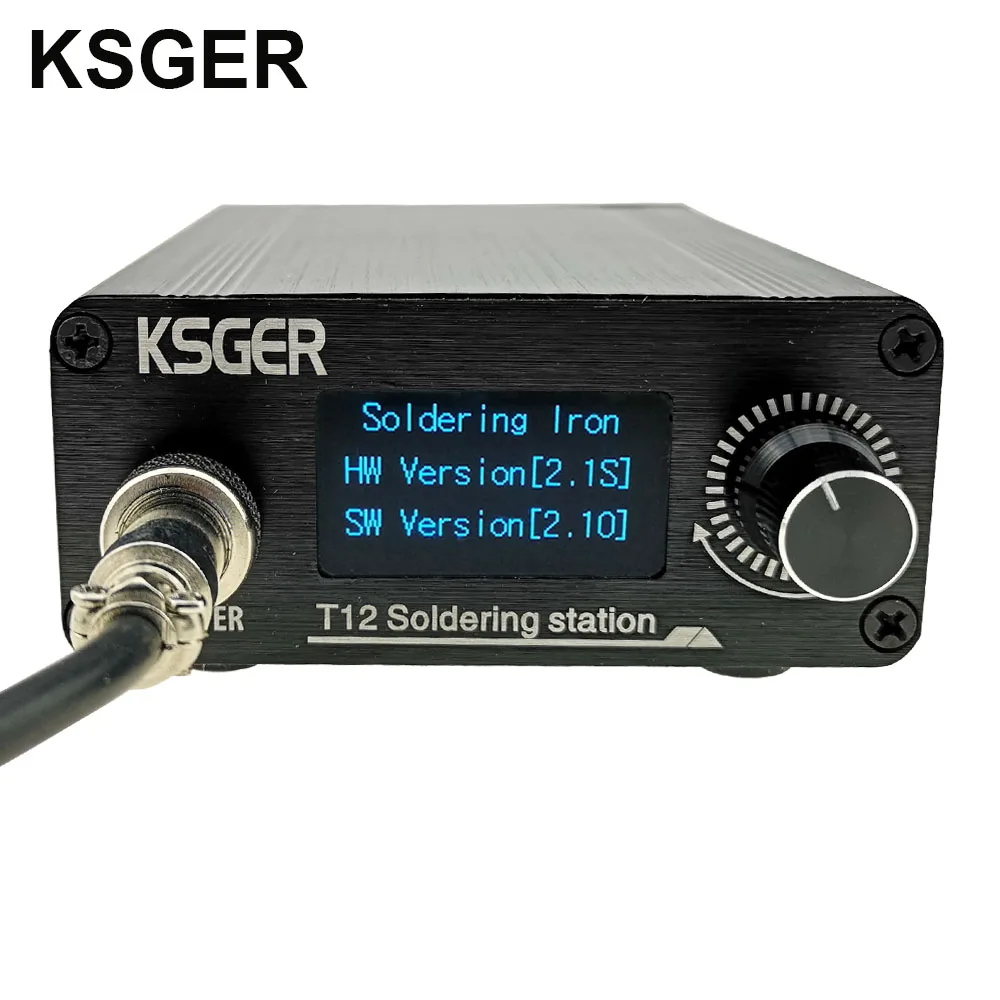
KSGER T12 Soldering Iron Station Lithium Battery STM32 V2.1S OLED T12 Iron Tips Aluminum Alloy
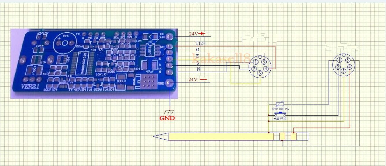
Re: handskit solder station t-12 wiring diagram. It will work without temperature sensor, using the stm32 built-in, but it seems there's a small smd sensor in the board itself. - H/T+ is the heater positive (First one, closest go the end of the cartridge). - G is the negative (second ring in the tip). - Earth is the bottom pin (The one with the.

Build Yourself Hakko T12 Compatible Soldering Iron Station Hendro's
What's inside the T12 soldering iron tip Apour Maker 19.2K subscribers Subscribe 259 Share 25K views 3 years ago Last time I made a T12 digital soldering iron station,It works well and.

soldering gun diagram
The white wire goes to the RTD (using COM as the other terminal). It measures around 8.6k at room temperature. The DIN8 connector pin 1 is hot/TC (24V), 2 is tip (500 ohm to earth), 3 is COM, 5 is RTD, 6 is LED (powered from 5V with 1SS396 diode and 390 ohm in series (plus a bit of reverse voltage protection), shield is earth.
Ksger 5pcs t12bc2/t12i/t12b/t12k/t1224 soldering iron tips soldering tips Sale Banggood
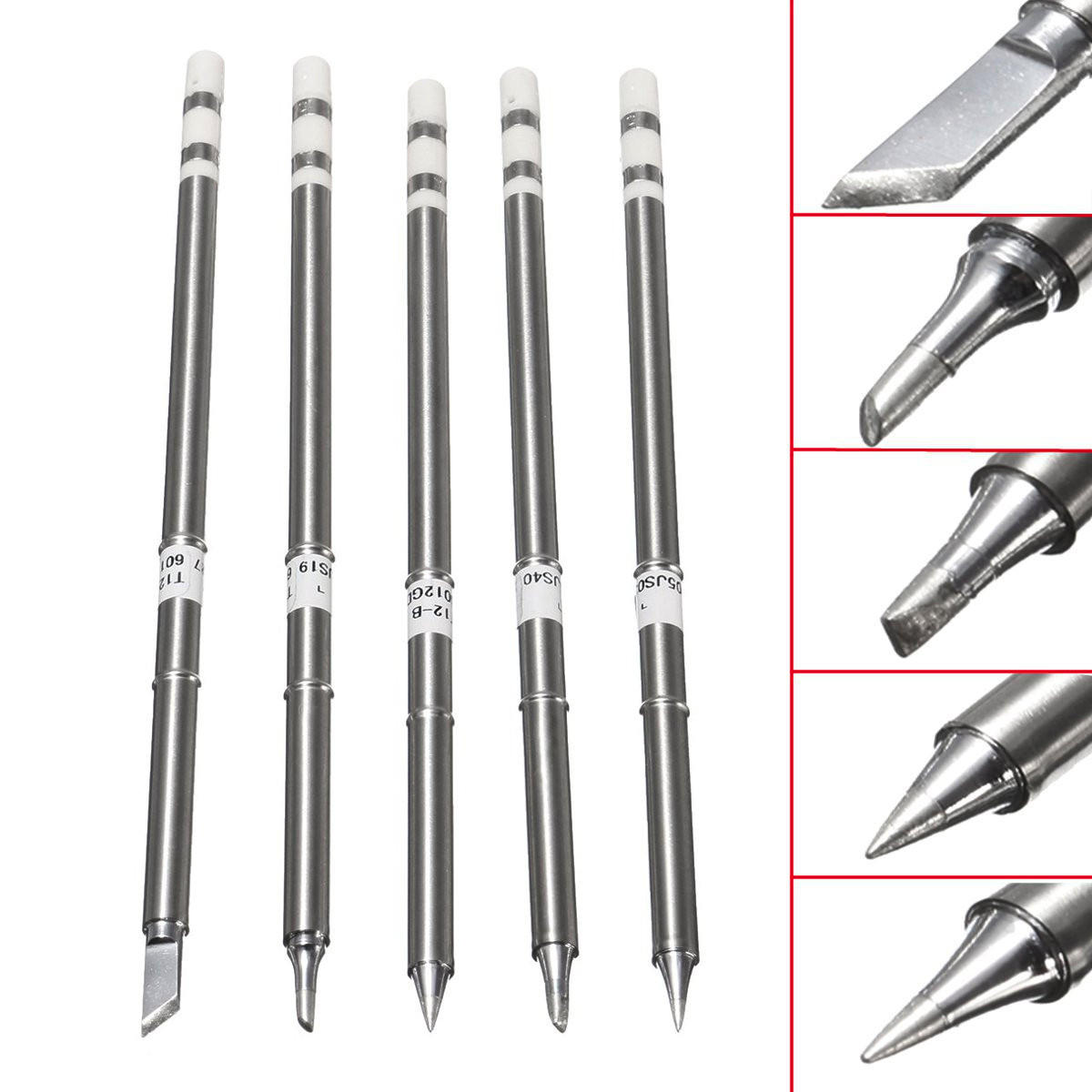
T12 Soldering Station Kit Soldering Station Aluminium Enclosure Soldering Iron Stand Soldering Station 24V 4A Power Supply T12 Soldering Iron Tip Various Types Brass Standoffs Kit M3 Screw Kit Heatshrink Tubing Kit The kit includes a T12-K soldering tip but since these tips are inexpensive I suggest you get yourself a couple of other tips as well.

Soldering Iron Pinout
How to build a Hakko T12 temperature controlled soldering iron. I show the complete build process and point out any potential problems. The video shows the build and the following steps explain the process. The kit is available on this link : HAKKO T12 Kit

T12 Electric Soldering Iron Tips T12K B2 BC2 ILS JL02 D24 KF For Hakko fx951 DIY Soldering
To know the temperature of the soldering iron tip, one has to add the temperature of the soldering iron handle (the cold junction temperature) and the temperature given by the thermocouple. To measure the temperature in the soldering iron handle, three sensors are available: CPU, NTC, and DS18B20. CPU Temperature sensor
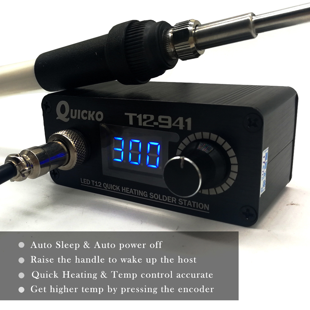
New QUICKO T12941 MINI T12 LED Soldering Station Eectronic Soldering Welding Iron with Handle
the T-12 tip seems genuine and has a variety of Hakko T12 replacement tips for it. This kit is fairly popular, here is an introductory link. Assembling the kit I bought just the kit without the enclosure nor the PSU. I laser cut the enclosure myself using 3mm MDF and for the PSU I use an idle laptop adaptor found on my desk.

t12 soldering station pcb for arduino connection EasyEDA
Soldering Iron Controller for Hakko T12 Tips on STM32 - Hackster.io Alexander Published June 11, 2018 © MIT Soldering Iron Controller for Hakko T12 Tips on STM32 Using STM32 to build a soldering iron controller. This time with a graphics OLED display. Intermediate Work in progress 3 hours 43,893 Things used in this project Story

DANIU Digital Soldering Iron Station Temperatures Controller Kits For Hakko T12 eBay
Step 1: Soldering LED, Vibration Switch, and 5pin Connector Yes, you do need a soldering iron to assemble this soldering iron. The first thing to do is to solder the red LED on to the main control board. It should be fairly obvious where this goes - no trickery here. The 5 pin connector gets soldered in to the left hand of the board.